The suspension of a car is what holds the wheels to the chassis, and is critical to good handling.
The front features an M Double Wishbone suspension.
"Double-Wishbone" means that that there are two main supports for the wheel, each of which looks like a wishbone. In the illustration above these as (2) and (5). There is also a "trailing link" (8) for additional support. The car is steered by means of the track rod (7) hooked up to the steering box (11).
In the F10, but all components are M-specific. There is also a 2.45 cm anti-roll bar (10) and a stiffening plate (12). The axle is attached in a more rigid fashion to the chassis than is usual, promoting increased torsional stiffness for better handling. It is made mostly from Aluminium to save weight.
The double wishbone in the F10 is an improvement over the McPherson strut system in most other cars, and also the E60 5-Series. With the MacPherson strut, the springs and dampers hold the weight of the car. With the double wishbone, they do not, and the springs and dampers are therefore more able to do their jobs. The MacPherson strut cannot allow vertical movement of the wheel without changing geometry relative to the road surface. The double wishbone is inherently superior in this regard. The MacPherson strut also transmits road noise and vibrations to a greater extent than does the double wishbone. Finally, the double wishbone allows for more freedom in the setting of camber and roll centre thus allowing the engineers to provide a better setup for handling purposes. The double wishbone tends to be more expensive and complex than the MacPherson strut, and it also can handle a heavier car.
The rear axle is also mainly made of Aluminium and is as follows.
It is an M Integral IV multi-link suspension with a 2.15 cm roll-bar (2), stiffening plate (1), and is directly attached (without rubber bushings) to the chassis for increased stiffness. Attaching the axle to the chassis without rubber bushings is uncommon in street cars, but standard for race cars. It is possible in the M5 because the base F10 starts with a very stiff chassis to being with.
This suspension incorporates “elastokinematics” that allow each wheel to move and flex individually without loads and forces through the subframe to the opposing wheel. It has been in use since the E39 5-Series, and the one in the F10 M5 was taken virtually unchanged from the E60 M5.
The standard F10 has moved on to the Integral Link V, as it supports rear wheel steering that assists in parking and in stability control. The M5 eschewed rear wheel steering as being not worth the weight.
As with any suspension, there are springs and shock absorbers at all four wheels. The springs allow the wheels to bounce up and back down when hitting bumps, the shocks prevent them from continuing to bounce.
The shocks in the F10 M5 are under electronic control, and can be stiffened or loosened very quickly in response to changing situations in order to optimize both comfort and handling.
The system is called M VDM (for M-Specific Vertical Dynamics Management). The shock absorbers were developed with ZF Sachs and adapted to the M5. This is the VDC II (Vertical Dynamics Control System II) system that uses independent extension (A) and compression (B) adjustment via two sets of valves and works on the frequency at which the body of the car is oscillating to damp it.
The M VDM control unit gets signals from ride height sensors. The Electronics Damper Control (EDC) works with infinitely variable valves in the dampers. The hydraulic oil flow is regulated by the electromagnetic control valves. Control variables such as the ride height, front wheel speeds, steering angle, body movements and damper piston speed are used. Vertical acceleration between the suspension and body is monitored by the ride height sensors of the headlights. There is one ride height sensor installed at the front left and one at the rear left. They are hard wired to the Integrated Chassis Management control unit which sends these signals over FlexRay to the M VDM control unit.
The fundamental control principle is known as the “Skyhook system”, because the primary objective is to hold the vehicle stationary in a vertical direction. An overall analysis is performed of the ride height data, z-axis acceleration rates, and steering inputs (e.g. transition from straight-ahead travel to cornering). If M VDC detects a rapid increase in the steering angle, the controller infers that the vehicle is entering a bend and can preventively adjust the dampers on the outside of the bend to a harder setting in advance. Moreover, VDC is able to detect the braking operations by the driver based on the brake pressure information supplied by DSC. A high brake pressure normally results in pitching of the vehicle body; VDC counteracts that effect by setting the front dampers to higher damping forces. This also results in an improvement in the front/rear brake force distribution, which in turn reduces the braking distance.
The driver can set the system to Comfort, Sport, and Sport+ for increasing levels of stiffness.
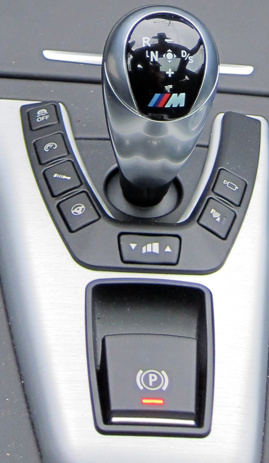
This set by means of the shock absorber symbol near the gear shift lever (third from the top on the left).
A blog about the BMW F90 M5 car in particular, and about how modern cars work and came to be in general.
Sunday, 17 February 2013
Chassis
The chassis of the car has dimensions in millimetres as follows.
The incoming F10 is slightly larger than the E60 in all dimensions.
The body is made from lightweight materials including aluminium, multiphase steels and very high strength press-hardened hot-formed steels. The average strength of all body materials has increased by 55% as compared to the E60.
The monocoque metal shell is shown above. The body struts in the engine compartment are all of die-cast lightweight aluminium as opposed to a conventional steel shell structure.
Here we see the distribution of materials. Aluminium (green 3) is used for hood and door panels. Multiphase steels with tensile yield strength >300MPa (44,000psi) (1) are used in many parts, and super-high-strength hot-formed manganese-boron steels with a strength >900MPa (2) are used in certain critical location. The rest (4) are other steels <300MPa.
The unit of strength MPa is a Mega-Pascal which is millions of Newtons per square meter. For comparison, Titanium alloy starts breaking at 940 MPa, Aluminium alloy at 414 MPa.
The goal of the choice of materials for the chassis is structural integrity, stiffness of the chassis (for cornering purposes), light weight, and getting as close as possible to a 50-50 weight distribution, front and rear, which also promotes better handling.
Tires and Wheels
The tires on a car are a critical factor in its performance. Having bad tires on a great car would be analogous to having crummy speakers hooked up to a fantastic sound system.
The wheels on the M5 are forged alloy and are either 19" (1) or 20" (2). This dimension refers to the diameter of the wheel itself, not the wheel+tire diameter. On my M5 I have 19" wheels for the winter tires, and 20" for the summer tires.
It is important that the wheels be as lightweight as possible, because they act like a gyroscope and resist turning if too heavy. Also, they are part of the so-called "unsprung" mass of the car, that part of the car which is isolated from the heavier chassis. Lighter unsprung mass means that the wheels will more readily conform to the road surface, promoting better traction.
The summer tires are Michelin Pilot Super Sports. The front tires are 265/35R20 at the front, and 295/30R20 at the rear. The "295" part is the width of the tire in millimetres, or 11.6" wide. The "30" part is the ratio of tire width to tire sidewall height. So the sidewalls are 295 * 30% = 88.5mm = 3.5". Therefore the diameter of the tire and wheel together is 27". The summer tires are rated for very high speed, and the tire has been customized by Michelin specifically for the F10 M5. The tires would be extremely poor for winter driving, as the grippy rubber compound becomes hard like a hockey puck when too cold.
The tire has two types of tread rubber. The outboard shoulder features a track-type compound to withstand the stresses of high performance cornering while the notched centre ribs and inboard shoulder feature a compound designed for superior performance at very high speeds and in wet conditions. The tire's internal structure has twin steel belts reinforced by a spirally wound Twaron cord. Twaron is a polyamide cord that offers a lightweight, high-strength reinforcement above the steel belts.
The winter tires are Pirelli Winter 240 Sottozer Series 2.
They are 255/40R19 all around. The narrower tire is better for traction in the snow. It concentrates the weight of the car onto a smaller patch to allow for better grip in the snow. However traction on dry pavement is less good due to the smaller contact patch with the road. The rubber, however, stays soft even in the cold. The tire is optimized for winter driving, high speeds, and great handling.
Unlike on most BMWs, the tires are not "run-flat" models. The very stiff sidewall on a run-flat compromises grip and handling, and so is not deemed suitable for an "M" car. However, neither is there a spare tire in the trunk due to space and weight considerations. Instead we get a "kit" that attempts to seal and re-inflate a punctured tire.
Hmmmm....
Friday, 15 February 2013
Brakes
The F10 M5 is fitted with very large and efficient brakes for bringing its 4000+ lbs quickly from high speed to a standstill, or for dropping the speed quickly for corner entry.
The front brakes are M specific and use a large 15.7" ventilated and cross-drilled compound brake disk (aluminium centre, steel disk) combined with six-piston fixed calipers.
The disks are ventilated, meaning that they are hollow with a plate on each side. They are also cross-drilled, which provides more ventilation and a lighter weight.
The floating calliper system is shown below.
Here we see a typical arrangement of pedal to power brake booster to master cylinder, and then off to the front and rear brakes respectively, with hydraulic fluid returning on the left.
The front brakes are M specific and use a large 15.7" ventilated and cross-drilled compound brake disk (aluminium centre, steel disk) combined with six-piston fixed calipers.
The rear brakes use the same type of disks (but a touch smaller at 15.5"), and have a single-piston floating calliper which includes the electromechanical parking brake. The rear is taken from the base 550i, but painted racy blue!
The front brakes do more work than the rears as the weight of the car shifts towards the front during hard braking and therefore there is more traction available at the front and more braking force needed there.
The steel outer ring is completely symmetrical, so when it expands due to heat it does so uniformly without introducing any bends or kinks that can rub against the brake callipers As the brakes cool you hear them "ping ping ping" as the outer disk collapses back onto the inner aluminium ring via the pins.
The disks are ventilated, meaning that they are hollow with a plate on each side. They are also cross-drilled, which provides more ventilation and a lighter weight.
The front brakes are six-piston fixed callipers and the rear brakes are single piston floating calliper.
Disk brakes have brake pads that squeeze against a brake rotor to slow the car door. There are two types of brake callipers at the wheels: fixed and floating.
The floating calliper system is shown below.
It uses only a single piston that pushes against one side of the brake disk that then pulls the calliper over to make contact with the other (bottom left).
The fixed calliper system is as follows.
There are pairs of pistons that squeeze down on the brake pad from both sides simultaneously. the M5 has three such pairs, hence it is a six-calliper brake. Fixed calliper systems are more effective than floating, but more complex and expensive.
The brakes are power-assisted using the traditional time-honoured approach. Brakes use hydraulic lines to transfer force from the brake pedal to the pistons and callipers.
Leverage combined with hydraulic force multiplication translate a relatively longer travel on the brake pedal into a shorter travel at the brake pistons at a much higher force. The diagram above illustrates the basic mechanisms at work. In this example, the force at the brake pedal is multiplied by a factor of 3 by the leverage and by a further factor of 3 by the hydraulics.
By law, all brakes have two isolated subsystems, one for the front brakes and one for the rear, in case a brake line fails.
The master cylinder is a clever arrangement that ensures the system does not empty of hydraulic pressure and keeps functioning even when one or the other of the sub-systems leak.
Most power brake systems use a vacuum booster to assist braking. The brakes use a brake servo which is powered by the vacuum generated by the engine. In the M5, because it is turbocharged, vacuum is in short supply in the intake manifold, and so a special vacuum pump maintains a reservoir of vacuum in a can, ready to be used to assist breaking on demand.
When the brake pedal is depressed hard enough, an air valve is opened which allows atmospheric pressure into one side of a vacuum chamber that boosts the pressure applied to the master cylinder.
Here we see a typical arrangement of pedal to power brake booster to master cylinder, and then off to the front and rear brakes respectively, with hydraulic fluid returning on the left.
For each brake there is also the Anti-Lock Braking system that contains electronically controlled valves and an electric pump that modules brake pressure when wheel lock-up is about to occur.
The purpose of ABS is to shorten the braking distance and to retain manoeuvring during braking so that obstacles can be avoided. When a brake is applied until it locks up, then the car starts sliding on its tires. Once the tires start sliding, they are actually less sticky. By pulsing the brakes, they are kept just on the threshold of lockup, which is the most effective for stopping. When driving without ABS, drivers must feel the point at which the brakes are just starting to lockup, and then ease off a bit to keep the wheels spinning. This is called "threshold braking", and is more effective than "pumping the brakes" but harder to master.
When brakes lock up, since there is no traction at all, there is certainly no traction for manoeuvring. The driver can turn the steering wheel round and round but the car will keep sliding in a straight line. With ABS, the car is kept on the threshold of traction, so traction is made available when the steering wheel is turned to steer the car away from obstacles during braking.
The system in the M5 pulses the brakes very quickly, can apply itself to the four wheels independently, and is completely under computer control. This system is used for a variety of additional stability control purposes in addition to the standard "Anti-Lock Braking" (ABS) function, all under the control of a sub-system calls "Dynamic Stability Control" (DSC).
Under normal braking conditions, hydraulic pressure from the master cylinder passes straight through to the brake pistons. The computer compares the wheel speeds against one another. If it detects a wheel locking it can isolate that brake from the driver's foot, and then bleed pressure off and then on again very rapidly. In order to recover pressure after the bleed, a pump is used to restore it. The operation of the pump and the valves is felt in the driver's foot as pressure pulsations when the system is regulating braking.
Additional braking functions in the M5 include the following.
- Cornering Brake Control (CBC) which applies brakes differentially when cornering with light braking;
- Dry Braking which applies 1 bar of pressure on the rotors for 1.5 s every 90s to dry the brakes when the windshield wipers are on continuous mode;
- Brake Standby which looks for a quick release of the accelerator pedal and pre-tensions the brakes with 2.5 bar of pressure for 0.5 s in anticipation of hard braking;
- Dynamic Brake Control which monitors speed and brake pedal pressure changes and goes to maximum braking pressure when warranted;
- Automatic Soft-Stop which automatically reduces pressure at the rear axle just before the vehicle comes to a stop when braking lightly;
- Fading Compensation which monitors brake effectiveness and provides additional pressure when brakes start fading;
- Drive-off Assistant which holds the brakes until sufficient torque is available when on a hill.
- The brakes are also requested to apply themselves to various wheels by the chassis dynamics system discussed later.
The rear brakes incorporate an electromechanical parking brake that is an independent system for clamping the callipers down on the rotors. It will work when parked and when moving (as per government regulations).
A motor is used to turn a spindle that applies locking pressure. When the motor is off, the pressure is still held as it is "screwed down" tightly.
The system is operated from a switch on the centre console under the gear lever. Pull up on it to apply. Push down to release. It can also be released by pressing on the accelerator.
There is a manual release buried under the trunk.
There is an additional system in the car related to braking called "Brake Energy Regeneration". In most cars, the alternator is continuously run whenever the engine is turning over. In this car, when accelerating or coasting the alternator is disconnected leading to a smaller engine load and more efficiency.
As long as the battery stays above a certain threshold, the only time the alternator is connected and drains shaft energy is during braking, either by means of engine overrun or when applying the brakes directly.
Differential
The purpose of the rear differential is to transfer the longitudinal rotary torque of the prop shaft 90 degrees to the wheels, while allowing the wheels to spin at different rates for when going around curves (the outer wheel needs to travel further than the inner). Here's how a differential works in general terms.
The input shaft spins the cage which tumbles the freely rotating blue "spider" gears. As they tumble, the green axles are spun. When the spider gears spin on their own axis, it allows one of the green shafts to turn at a different rate than the other.
In situations where the tires have different traction, a regular "open" differential as described above will direct all the torque to the tire with the least traction. This is a bad thing when going around curves as weight will transfer to the outer wheel and the inner wheel will lose traction. So just when you want more torque going to the outer wheel that has traction, it won't go there, and the torque will just spin the inner wheel uselessly. Likewise for when starting on snow and ice and one tire has more traction than the other.
For this reason, various "limited slip differentials" have been invented over the years. They use clutch plates to lock one of the axles to the cage thus preventing the blue spider gears form rotating about their own axis. Until recently, these have all been of mechanical design. The innovation in the M5 is to have these clutch plates operated by an electrical motor under computer control.
A cutaway of the unit is shown below.
The input shaft enters from the far side. The rear wheel axles are connected to the sides. The protruding device on the right is the computer-controlled motor which tightens and loosens the clutches. Here is another view.
We can see the electric motor which tightens up the clutches.
In this image, we see the inner workings at the front. The large bearings and worm gear that turn the cage are seen clearly.
The control unit (1) is under the trunk of the car near the battery.
It communicates with the central gateway module using the new FlexRay car computer bus standard, indirectly getting information from the stability computer (wheel speed, target transverse torque distribution, stabilization status, braking value), the motor electronics (accelerator pedal angle, wheel drive torque, "engine running" signal), and the integrated chassis management computer (wheel circumferences, lateral acceleration, yaw speed, vehicle speed, roadway inclination, steering angle).
Every 1000 km a quick calibration is run to correlate locking torque with motor current, and also assess clutch wear. The diff contains its own fluid, cooled by a heat exchanger, which are the veins underneath the unit in the under-vehicle airflow.
The operation of the limited slip rear differential is very noticeable when accelerating hard out of corners, especially in situations where the traction is limited. In my previous car, the E60 545i, the traction control would cut in in these situations, applying brakes and cutting engine power. Without traction control, you would need to accelerate out of the curve slowly or risk losing the rear end. In the F10 M5 by contrast, the car feels amazingly composed at speeds which would have easily spun out the other car.
Thursday, 14 February 2013
First Impressions
My new M5 finally arrived on the weekend! I took some photos.
Here are my impressions after a week of driving it around.
- The handling is absolutely amazing. It's on a different level entirely from other cars I have driven. That "M" logo on the steering wheel certainly stands for something.
- The power in the car is awesome to experience.
- Brakes are no-nonsense. They do a much better job than they appear to from the "lack of drama".
- The car is very comfortable and almost all the gadgets work as advertised (including the real-time traffic on the nav). The Blackberry integration for email messages is a bit hit and miss though.
- It feels like a big car when parking it.
- When driving, it feels big on the inside, but feels lithe and nimble on the outside.
- The car has a very different character in "Comfort" settings (the default when it starts up), as opposed to the sportier settings available when you press a pre-programmed "M" button. Turns into an absolute beast in M mode!
- I am very happy with my colour and trim selections.
- I look forward every single day to driving her!
Wednesday, 13 February 2013
Dual Clutch Transmission
The drivetrain is shown below. The gearbox is mounted longitudinally, in line with the engine crankshaft and connected via a driveshaft to the rear differential which directs torque to the wheels, tires, and road.
The gearbox on the M5 is the Getrag GS7D36BG M Double-Clutch Transmission (DCT) with Drivelogic. The "Drivelogic" is marketing speak for the computer that controls the gearbox: BorgWarner's DualTronic clutch module (also called the "mechatronics" as a hybrid of mechanical and electronic in one package).
It is classified as an "Automatic Manual" because it uses clutch plates and a clutch mechanism to connect and disconnect the engine from the geartrain as for a manual transmission, but is has no clutch pedal and the gears can be made to shift automatically as for an automatic. It does not use a fluid-coupled torque converter as would a traditional automatic transmission, instead using hydraulically controlled wet clutches.
It is a "Dual-Clutch" because it has two set of clutch plates, one for the even gears and one for the odd ones. This creates two sub-transmissions. As one is driving along in a certain gear using sub-transmission A, the electronics know if you are accelerating or decelerating, and will automatically engage the next gear in advance on sub-transmission B. This sub-transmission B free-wheels until the one clutch is disengaged and the other engaged. This allows extremely rapid gear changes with no interruption of power to the wheels.
This type of transmission was first used on a BMW in the M3. The Getrag BG used in the M5 is a beefed-up version of the SG used in the M3, and shown below in a partial cut-away view.
The principle of operation is as shown below.
The engine (A) inputs torque to two clutch assemblies (1,3) within the transmission (B). Depending upon which clutch is engaged, torque flows to either the top transmission sub-assembly (2) or the bottom one (4). These gears engage the propeller shaft which drives the rear wheels through a differential (C).
The dual-clutch assembly pulled away from the gear trains is shown above. It is a wet clutch, meaning that it is bathed in oil for smoother operation and longer life, and uses multiple clutch plates to compensate for any resulting slip. The two clutches are concentric, and the two transmission sub-assembly shafts nest one inside the other (observe the nested toothed gears towards the middle right, each drives its own sub-assembly).
The illustration below represents the inside of the M3 gearbox, but it is similar in principle to the M5's. The gear train on the bottom is called the countershaft. It is permanently rotating and meshed with the constant gear on the output shaft. There is an additional small gear train sticking out the side for reverse gear. The various gears are always meshed with one another. Some are permanently rotating with their shaft, others are free-wheeling on their shaft until a dog clutch pushed in place by the shift mechanism meshes them to their shaft. The dog clutch uses a synchomesh mechanism to match RPMs before locking the gear to the shaft. The main shaft is actually two entirely separately rotating shafts, one nested inside the other. Some of the dog clutches mesh the gear to the inner shaft, others to the outer shaft, and some of the gears are permanently rotating with either the inner or outer shaft.
Below we see the gear diagram showing sensors. The blue rectangles are the sliding dog clutches. They slide right or left to "mate" a gear to its shaft. Each has its own shift travel sensor.
For example, 2nd gear is always turning with the main outer shaft, and it is meshed with its counterpart on the countershaft. That gear, however, is free-wheeling on the countershaft until the dog clutch mates with it.
The system predicts what gear it will likely go to next depending on if the car is accelerating or decelerating. It will then pre-engage the appropriate dog clutch. The next gear is always on the other shaft which is not yet clutched to the drive shaft, so its shaft can free-wheel. The engaged clutch can then start decreasing and the other clutch can start increasing in pressure to match RPMs.
The following animated diagram shows all the various power channels through the transmission.
Note how the clutches alternate as we go up and down the gears.
The diagram below shows the entire system.
The transmission (2) is lubricated and cooled by oil via the air/transmission oil cooler (1). The transmission has its own integral oil pump driven from the center input shaft. Therefore the engine must be running for the oil pressure to build up. It is connected by wires to the gear selector level.
Within the transmission there is a pipe running down the side with nozzles to lubricate the gears.
On the drive end of the casing there is the parking brake that prevents the shaft from moving, with the mechanism shown below.
Park is engaged when the engine is turned off and the gearbox is not in neutral. If the parking brake ever needs to be released manually, this is accomplished inside the front cup holder by removing the cover and sliding the parking lock lever as shown.
The "mechatronics" (electronics + hydraulics) module plugs into the side of the transmission, receiving input from the various position, rotation, temperature, and pressure sensors within, and effecting via hydraulics the shifting and clutching functions.
The mechatronics communicate with DME-1 via the PT-CAN computer bus to get pertinent information and to "blip" the throttle on shifts. Blipping means bringing the engine revs up to match the wheel speed at the next lower gear down during down-shifts. The gearbox blips in all shifting modes.
Sequential manual gear shift control can be effected by the '+' and '-' paddle shifters on the wheel.
The main control is by means of the gear shift selector.
Moving the selector to the right toggles between "Drive" (automatic shift) and "Sequential" (manual shift). Pushing the lever forward and back will shift. Pushing the lever to the left will engage neutral. Left and up: reverse.
Each of D and S modes have three "Drivelogic" settings accessed from (5). In D these are Efficient, Comfortable, and Sporty, which will move the shift map higher in the RPM range and shift faster. In S mode, the three are Comfortable, Sporty, and Maximum which refer to the speed of the gear changes. The shifting speed is also affected by the accelerator position and how quickly it is changed. In my experience, D1 mode is dreadful in that it robs the car of all its torque by shifting too early and keeping the revs very low. This is the most fuel efficient setting, however.
There is a mode called "Launch Control" for maximal acceleration off the line allowing the optimal amount of wheel slip (17%) and using the fastest shift speeds at the highest RPMs. This is engaged by deactivating DSC, selecting the third "S" mode, pressing the brake pedal gently, holding the gear selector forward, waiting for the flag symbol to appear, flooring the accelerator, releasing the brake, and then releasing the gear selector switch. It's not meant to be easy!
In order to simulate the bahviour of an automatic gearbox, a light tap on the accelerator when stopped will cause the car to move forward (or backwards if in R) very slowly without holding it. On hills, the brakes hold the car steady for 2 seconds after releasing them until the accelerator is depressed. After that, it starts rolling.
The gear ratios are as follows. 1st=4.8x, 2nd=2.6x, 3rd=1.7x, 4th=1.3x, 5th=1.0x, 6th=0.84x, 7th=0.67x. The final drive ratio at the rear differential is 3.15x. Driving at less than 145 km/h it's never necessary to get out of 3rd gear, though the RPMs are at 6000. 4th gear will get you to well above 200 km/h, and 5th will get you to its maximum speed of somewhere around 300 km/h (though the electronic speed limiter keeps it to under 240 km/h or so). 6th and 7th gears are for fuel economy, for cruising quickly on the highway at relatively low RPMs to conserve fuel.
The DCT gearbox on the F10 M5 is an absolute delight to drive. First it adds to the performance of the car by keeping power applied through the shifts. Second, the shifts are lighting quick, like gunshots, which is just a whole lot of fun to drive, and finally the blips on the downshifts are just right, and make it feasible to get yourself easily into the right gear when tackling a corner.
Subscribe to:
Posts (Atom)